Steel pipe burst pressure is a core parameter for pipe selection, pressure testing, and engineering design. It represents the maximum internal pressure a steel pipe can withstand before catastrophic failure.
For industries such as water supply, chemical processing, oil and gas transmission, and fire protection piping, burst pressure data is essential for calculating safe working pressure and selecting the correct pipe schedule.
This guide covers the Barlow formula, common steel pipe burst pressure charts, key influencing factors, and proper usage rules.
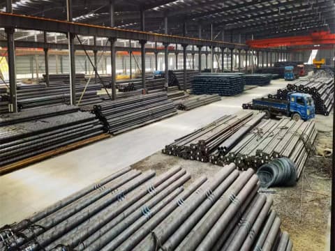
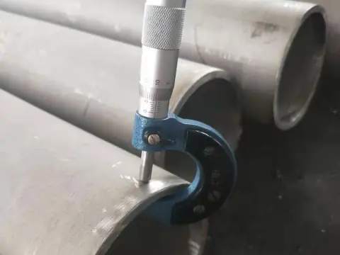
1. What Is Steel Pipe Burst Pressure?
Burst pressure is the pressure at which a pipe wall ruptures under internal pressure. It represents the ultimate pressure-bearing limit of the pipe.
For engineers, understanding burst pressure is critical for:
- Determining safe working pressure limits
- Selecting the correct pipe wall thickness / Schedule
- Ensuring compliance with design codes
- Preventing pipe failure and safety accidents
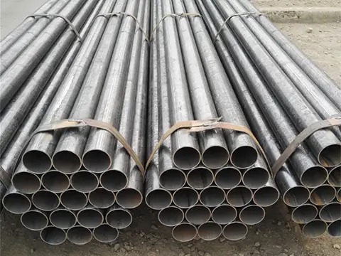
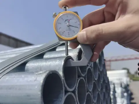
2. Barlow’s Formula for Steel Pipe Burst Pressure
The most widely used formula for calculating steel pipe burst pressure is Barlow’s formula. It is suitable for seamless steel pipes, straight-seam welded pipes, and other standard round carbon steel pipes.
Formula:
P = (2 × S × t) / D
Character Definitions
- P = Theoretical burst pressure (MPa or PSI)
- S = Tensile strength (MPa or PSI)
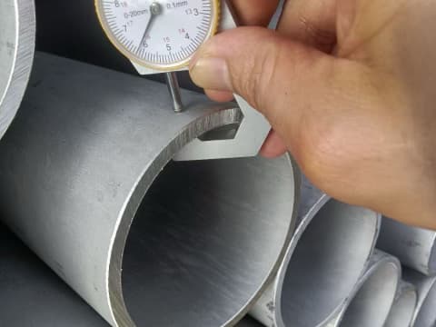
- t = Wall thickness (mm or inch)
- D = Outside diameter (mm or inch)
Important:
Barlow’s formula calculates theoretical burst pressure, not allowable working pressure. For safe engineering operation, the burst pressure must be divided by a safety factor.
Barlow’s formula is generally suitable for thin-wall pipes, where the wall thickness is less than about 1/10 of the diameter.
3. Steel Pipe Burst Pressure Chart
3.1 Schedule 40 Steel Pipe Pressure Chart
| 1/2″ | 10,380 | 1,300 |
| 3/4″ | 8,610 | 1,080 |
| 1″ | 8,090 | 1,010 |
| 1 1/4″ | 6,745 | 840 |
| 1 1/2″ | 6,100 | 760 |
| 2″ | 5,185 | 650 |
| 2 1/2″ | 5,650 | 710 |
| 3″ | 4,940 | 620 |
| 3 1/2″ | 5,610 | 700 |
| 4″ | 5,270 | 660 |
| 5″ | 4,630 | 580 |
| 6″ | 4,220 | 530 |
| 8″ | 3,720 | 470 |
| 10″ | 3,380 | 420 |
| 12″ | 2,930 | 370 |
Note: All values are theoretical burst pressure calculated by Barlow’s formula, for reference only.
Safety factor used in this table: 8:1
Unit conversion:
1 PSI = 0.06895 bar = 0.006895 MPa
3.2 Schedule 80 Steel Pipe Pressure Chart
| Nominal Pipe Size | Working Pressure (bar) | Burst Pressure (bar) |
|---|---|---|
| 1/8″ | 14 | 105 |
| 1/4″ | 14 | 105 |
| 3/8″ | 14 | 105 |
| 1/2″ | 14 | 105 |
| 3/4″ | 14 | 105 |
| 1″ | 14 | 105 |
| 1 1/4″ | 14 | 105 |
| 1 1/2″ | 14 | 105 |
| 2″ | 14 | 105 |
Note: Table data is transcribed from the provided image. Please verify the original values before publication.
Safety factor used in this table: 6:1
3.3 Steel Pipe Burst Pressure by NPS and Schedule
| NPS | OD (mm) | Sch10 / Burst | Sch20 / Burst | Sch40 / Burst | Sch80 / Burst |
|---|---|---|---|---|---|
| 2″ | 60.3 | 2.77 / 22.1 | 3.05 / 24.3 | 3.91 / 31.2 | 5.54 / 44.3 |
| 3″ | 88.9 | 3.05 / 16.5 | 3.68 / 19.9 | 5.49 / 29.8 | 7.62 / 41.5 |
| 4″ | 114.3 | 3.05 / 12.8 | 3.96 / 16.7 | 6.02 / 25.4 | 8.56 / 36.2 |
| 6″ | 168.3 | 3.40 / 9.7 | 4.78 / 13.6 | 7.11 / 20.3 | 10.97 / 31.2 |
| 8″ | 219.1 | 3.76 / 8.3 | 5.54 / 12.2 | 8.18 / 18.0 | 12.70 / 27.9 |
| 10″ | 273.1 | 4.19 / 7.3 | 6.02 / 10.4 | 9.27 / 16.4 | 15.09 / 26.6 |
Wall thickness in mm, burst pressure in MPa.
Notes:
- Sch10 / Sch20: Mainly used for water supply, ventilation, and low-pressure fluid transmission.
- Sch40 / Sch80: General-purpose schedules for industrial, chemical, and oil & gas applications.
- The values above are theoretical burst pressures. Working pressure must be calculated by dividing by the applicable safety factor.
4. Factors That Affect Steel Pipe Burst Pressure
4.1 Material Grade
Higher tensile strength provides higher burst pressure.
| Material | Tensile Strength (MPa) | Tensile Strength (PSI) |
|---|---|---|
| A53 Grade A | 330 | 48,000 |
| A53 Grade B | 415 | 60,000 |
| A106 Grade B | 415 | 60,000 |
| API 5L X42 | 415 | 60,200 |
| API 5L X52 | 455 | 66,000 |
4.2 Wall Thickness and Pipe Schedule
For the same pipe diameter, a thicker wall and higher schedule provide greater burst pressure.
Example: 2″ pipe:
- Schedule 40: 3.91 mm wall thickness
- Schedule 80: 5.54 mm wall thickness
- Schedule 160: 8.74 mm wall thickness
Pressure resistance order:
Sch160 > Sch80 > Sch40.
4.3 Operating Temperature
As operating temperature increases, material strength decreases, and burst pressure is reduced. High-temperature piping requires additional safety margin.
4.4 Corrosion and Wear
Over time, corrosion and external wear reduce wall thickness, significantly lowering pressure-bearing capacity.
4.5 Weld Quality
For welded steel pipes, the weld joint factor (E) reduces the calculated burst pressure.
- Seamless pipe: E = 1.0
- Welded pipe: E = 0.85 to 1.0
5. Burst Pressure vs Working Pressure
Burst pressure is the theoretical pressure at which the pipe ruptures.
Working pressure, also called Maximum Allowable Working Pressure (MAWP), is the safe operating pressure.
MAWP = Burst Pressure / Safety Factor
Burst pressure must never be used directly as working pressure.

6. Safety Factors by Application
Safety factors vary by application and applicable code. Common values include:
| Application | Typical Safety Factor |
|---|---|
| General industrial piping | 4:1 |
| ASME B31.3 process piping | 3–4:1 |
| Critical applications | 6:1 or higher |
| Water supply | 4:1 or per local code |
For water supply pipelines, engineers often require the pipe burst pressure to be at least 3–4 times the maximum system pressure.
For transmission pipelines, API 5L steel grades are commonly used, with design factors based on Specified Minimum Yield Strength (SMYS). Design factors may start at 0.72 in rural areas and drop to 0.60 or lower in populated areas.
Note:
Some Schedule 40 and Schedule 80 tables may use different safety factors, such as 8:1 or 6:1. Always confirm the basis of the table before use.
7. How to Calculate Safe Working Pressure
- Confirm pipe outside diameter, wall thickness, and material grade.
- Use Barlow’s formula to calculate theoretical burst pressure.
- Divide by the safety factor to obtain Maximum Allowable Working Pressure (MAWP).
- Adjust downward based on temperature and corrosion conditions.
8. FAQs
Q: What is the difference between burst pressure and working pressure?
A: Burst pressure is the theoretical pressure at which the pipe ruptures. Working pressure, or MAWP, is the safe operating pressure. It is calculated by dividing burst pressure by a safety factor.
Q: Does Barlow’s formula apply to all pipe types?
A: Barlow’s formula applies to thin-wall pipes, generally where wall thickness is less than about 1/10 of the diameter.
Q: What safety factor should be used?
A: The appropriate safety factor depends on the application and applicable code. Common values include:
- General industrial: 4:1
- ASME B31.3 process piping: typically 3–4:1
- Critical applications: 6:1 or higher
- Water supply: 4:1 or per local regulations
Q: How do I select the correct pipe schedule?
- Determine design pressure and temperature.
- Determine allowable stress of the material at design temperature.
- Calculate minimum required wall thickness using the applicable code formula.
- Select a schedule with wall thickness equal to or greater than the minimum.
- Verify the selection against ASME B36.10M or B36.19M dimensional tables.
Need Help Selecting the Right Steel Pipe?
Send us your pipe size, wall thickness, material grade, and working pressure. Our team can help you calculate burst pressure, recommend the suitable schedule, and provide a quote.
Contact us today for a custom steel pipe solution.